

Technical Articles · Replacement Windows
A flat replacement window needs its full outline, thickness and mounting features. A curved window also needs its surface shape and support conditions described. Clear labels make the information useful, even when some measurements are still missing.
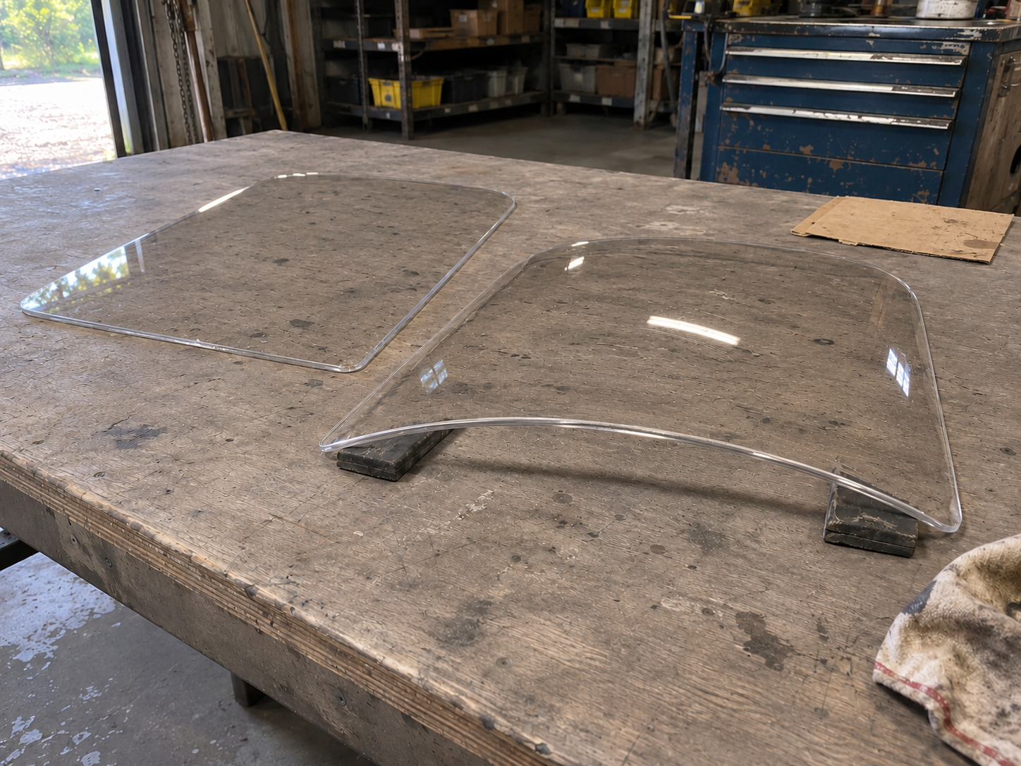
In this guide
Start with what you have: existing photographs, available dimensions and the quantity required. Identify the equipment and window position, and say whether the panel is installed, loose or missing. You can begin the discussion without commissioning a scan, creating CAD or removing the glass.
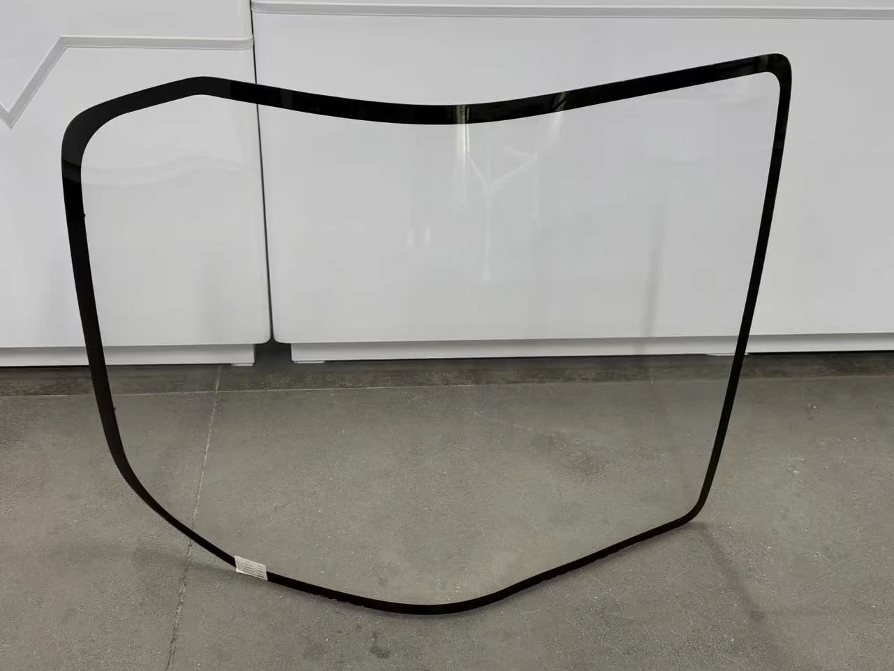
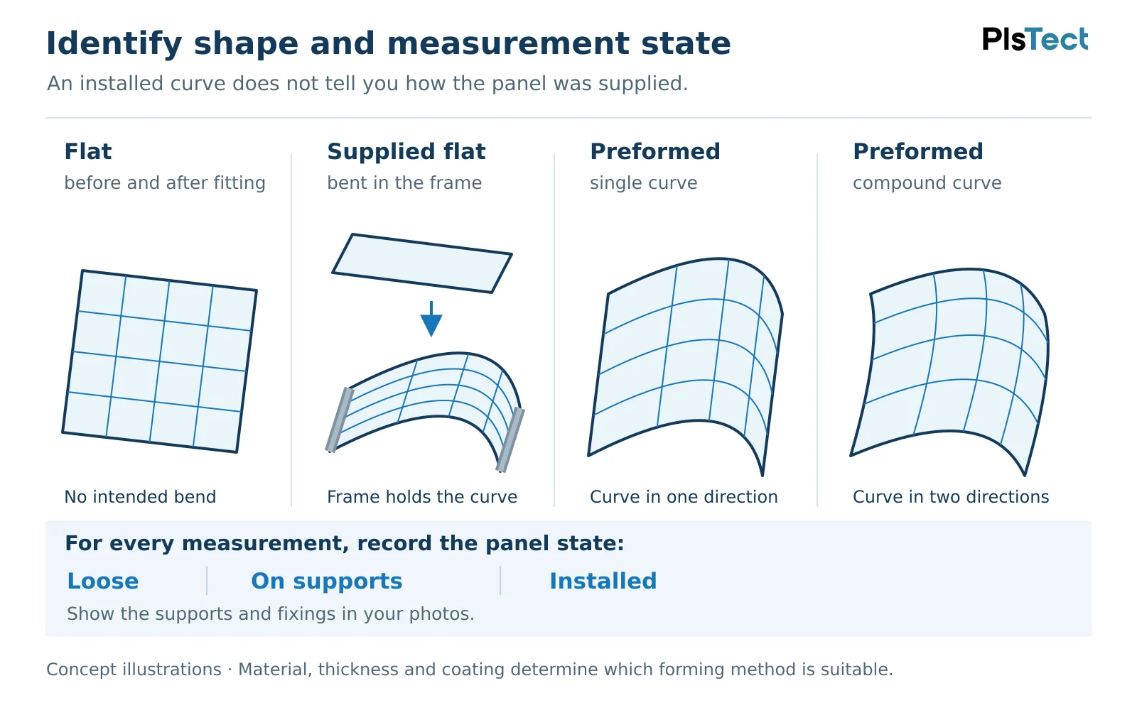
1. Identify the shape and measurement state
A window that looks curved in its frame may have been supplied flat or already formed. Record what you know about both its supplied shape and its installed shape. If the manufacturing route is unknown, say so.
| Window type | What needs describing |
|---|---|
| Flat when loose and installed | Full panel outline, thickness, holes, slots and mounting details. |
| Supplied flat, then bent into the frame | The unbent blank and the installed curve, including supports and restraints. |
| Preformed, mainly curved in one direction | Complete edges and identified sections, including changes in curvature and transitions to flat areas. |
| Preformed with compound curvature | The surface shape in more than one direction, plus complete boundaries and mounting features. |
Cold bending and thermal forming are different routes. Suitability depends on the selected material, thickness, coating and geometry; the appearance of the original does not establish that a proposed replacement can be bent the same way. [1]
Label each measurement loose, on supports as shown or installed in frame. Identify separately whether the reference is an unbent blank or a formed panel. Photograph supports, clamps and restraints. Flexible panels can change shape when support changes, so keep records from different states separate. Do not force a preformed original flat.
2. Give each curved measurement a clear name
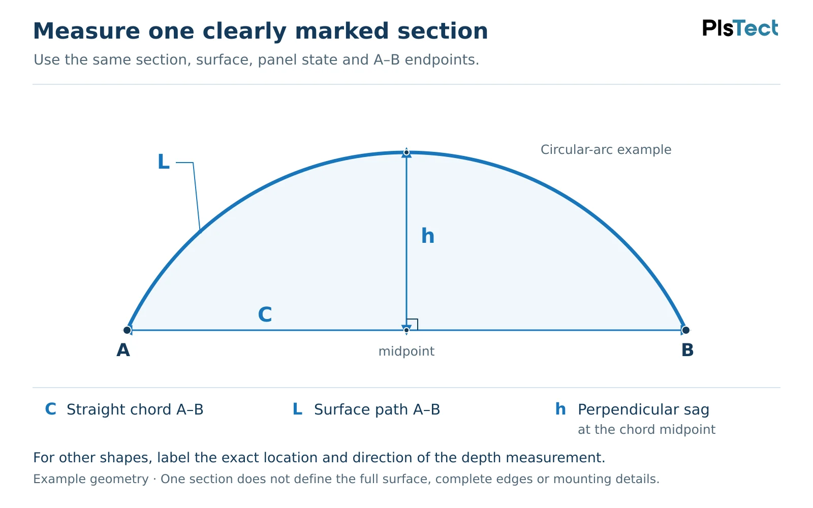
A straight span and a tape following a curve describe different lengths. Mark the section location, endpoints A and B, measurement direction and reference face on a sketch. Use one unit system.
| Label in the example | Measurement path |
|---|---|
| C — chord | The straight distance from A to B in the selected section. |
| L — surface length | The distance following the selected surface from A to B along that section. |
| h — sag | In the circular-arc example below, the perpendicular distance from the chord midpoint to the selected arc. |
Take the related measurements from the same section, face and state. Do not combine an OUTSIDE surface length measured in the frame with an INSIDE chord measured after release. A front-view projected width is another measurement; identify the view instead of calling every dimension “width”.
The midpoint definition of h applies to this circular-arc example. For a different profile, show where an offset was measured. One section or radius does not describe the whole window.
3. Record the edges, features and changing sections
A useful record connects the shape to the features that locate the window in its frame:
- Full panel edge: show corners, notches and cutouts. Identify the visible opening separately; edges hidden by seals or retainers remain unknown until confirmed. Do not add an assumed overlap.
- Thickness: record the original value, units and measurement location where safely accessible. Distinguish measured thickness from a drawing’s nominal value. The original thickness does not automatically set the replacement thickness.
- Holes and slots: identify centres, diameters, slot width, overall length and direction. Locate them from named reference edges or lines, and state whether distances follow the surface or use a specified projection.
- Mounting: show seating edges, seals, clamps, fasteners and any bonded overlap. Mark which dimensions control fit.
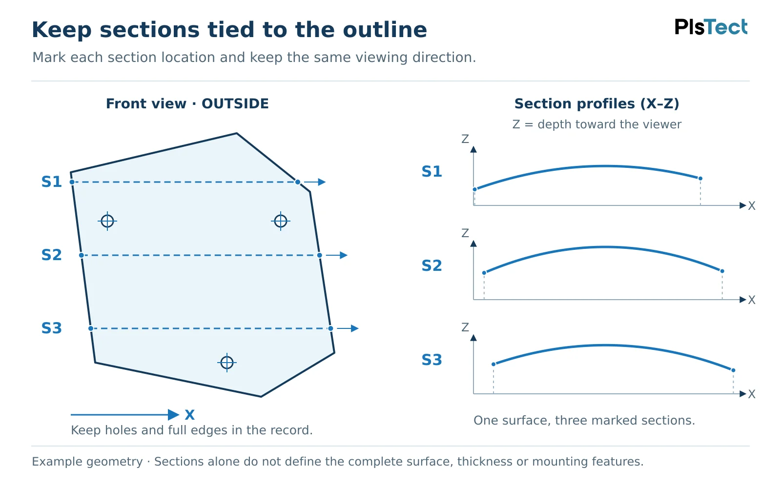
For a curved part, show where sections were taken, their direction and the face measured. Include regions where curvature changes, near mounting features and where curved areas become flat. Several sections can help compare the shape, but no fixed number guarantees a complete surface definition.
For a confirmed flat reference, follow the full-size cardboard template guide. A front-view outline of a curved panel cannot replace its depth information.
4. Prepare photographs and a first reference set
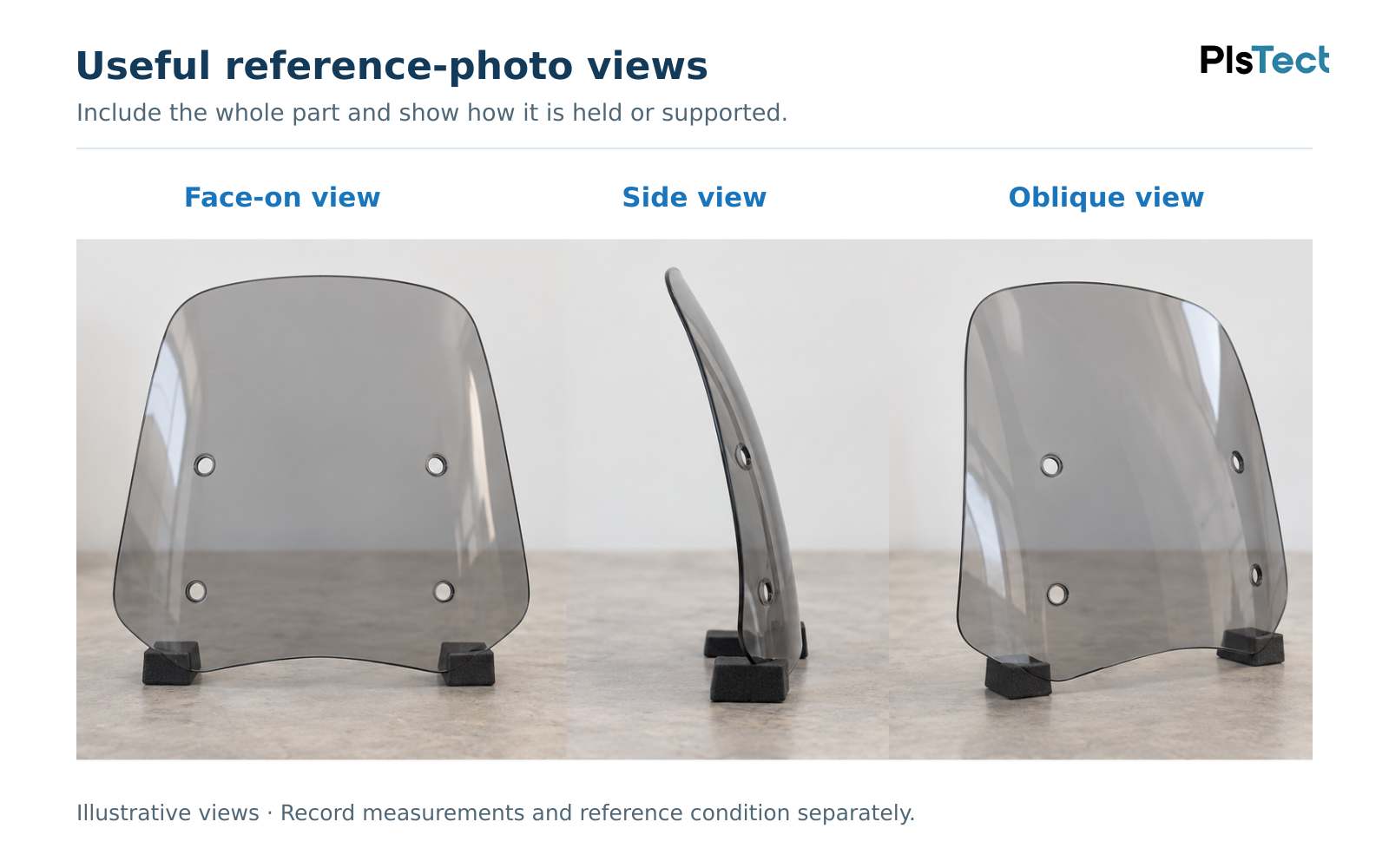
Photograph the same panel from several useful views, keeping its state consistent where possible:
- Front: the complete outline or opening and its equipment position.
- Side: the visible curve, edge and support arrangement.
- Oblique: how the curve and frame meet.
- Close-ups: mounting features, seals, damage and uncertain areas.
Label TOP and INSIDE/OUTSIDE, and define left or right from a stated viewpoint. Note any changed support between photographs. Ordinary photos help explain the part, but a ruler in the image does not establish a checked three-dimensional shape. Photograph installed or damaged glass in place; any required removal should be handled by qualified personnel.
Minimum information for the first discussion
- Equipment model, window position, part number if known, and quantity.
- Existing photographs and whether the panel is installed, loose or missing.
- Available overall dimensions and thickness information, with units and measurement methods.
- Any drawing, original panel or template already available.
- Known damage, hidden edges, missing measurements and proposed changes.
Use simple status labels: Measured for values actually measured, with endpoints, method, face and state recorded; Estimated for approximations, with their basis; and Unknown for unavailable information.
Send an incomplete record with the gaps marked. The next discussion can focus on the measurements that matter, rather than asking you to create a complete model first. Use the five-part quotation checklist for the other project details.
5. Consider specialist measurement when the shape warrants it
Complex curvature, inaccessible features or conflicting references may justify specialist measurement or scanning. Transparent and reflective surfaces can require an adapted optical-scanning method. [2] Discuss surface preparation with the service provider before altering the reference.
A scan mesh is not automatically a checked manufacturing model. [3] If commissioning work, agree three deliverables:
- Coverage record: captured faces, edges and mounting areas, with support conditions and missing regions identified.
- Usable files: required scan or CAD formats, units, reference face and alignment; identify reconstructed or filled areas.
- Check record: comparison with agreed critical dimensions and the stated measurement method.
A single scanned face does not establish the opposite face or thickness. Decide what is needed for this part before paying for capture or modelling.
Measurement questions
Is one radius enough for a curved window?
Only when the relevant shape is confirmed to follow that radius and the remaining geometry is defined. Identify the section and reference surface. A centre radius alone does not establish edges, transitions or mounting positions.
Can glass be the reference for a polycarbonate replacement?
Yes, it can help describe geometry. Record damage and features that should not be copied. Replacement thickness, material and mounting need their own review.
For the material-change decisions, see what to check when replacing glass with polycarbonate, including thickness, frame movement, sealing and surface performance.
What if we have no scanner or drawing?
Start with photographs, available dimensions and quantity. Mark what is unknown. A physical reference, additional section measurements or specialist work can then be considered for the missing information.
Related PlsTect support: Engineering Support · Formed Windshields & Windscreens
Further Reading
- Palram — PALSUN Technical Guide, printed pages 31–34. Product-specific cold-forming and thermoforming guidance; its numerical limits are not PlsTect specifications.
- Artec Studio 20 — Scanning. Guidance on surface-related capture difficulties and method selection for Artec equipment.
- Creaform — Scan-to-CAD. An example of mesh preparation, alignment and the subsequent extraction of geometry for CAD work.
Discuss your replacement window reference
Send the window photographs, available dimensions and quantity. Identify the equipment, panel position and measurement state, and mark unknown details. Ask which additional reference would be useful before arranging a template, scan or sample shipment.