

From Part Requirements to a Buildable Transparent Component
A material can meet the specification and still create problems later in coating, forming, machining, bonding or assembly.
Send us a drawing, CAD file, sample, existing part or even an early-stage requirement. PlsTect looks at the part as a whole and helps define a practical combination of material, surface function and manufacturing process before the project is locked.
Start With What You Have
You do not need a complete engineering package before contacting PlsTect. Different projects can begin from very different levels of information.
Drawing, CAD or Specification
If the part is already defined, we can review the material, geometry, critical dimensions, surface requirements and planned manufacturing steps together.
Existing Part, Sample or Assembly Reference
If drawings are incomplete, an existing transparent part, glass panel, frame, hardware set or template can help establish the geometry, installation interface and areas that need to be retained or changed.
Performance Requirement or Existing Problem
Sometimes the starting point is simply a requirement: reduce scratching, control static, improve visibility, withstand cleaning chemicals, form a curved part, or replace a component that is not performing as expected. We can use those conditions to identify the engineering questions that need to be resolved first.
The first review is not about completing every field. It is about separating what is already known from what still needs to be defined or proven.
Where Transparent Part Projects Become Difficult
Most problems appear when one decision changes another.
Engineering review connects the requirement, the material, the surface, the geometry, the manufacturing route and the final assembly before they are locked separately.
Material vs Final Requirement
The Requirements Pull in Different Directions.
A clear cover may need impact resistance, scratch resistance, optical clarity and chemical cleaning at the same time. Improving one condition can limit the material, coating or forming method available for another.
Surface Function vs Processing
A Downstream Process Changes the Surface.
Hard-coating that performs well on a flat sheet may be stretched during forming, marked during machining or affected by printing and bonding. The sequence has to be considered before the surface is specified.
Geometry vs Manufacturing
Geometry Changes What Is Manufacturable.
Tight bends, deep curves, small radii, holes near an edge and critical optical areas can change thickness, tooling, trimming and tolerance choices.
Component vs Assembly
The Part Has to Fit the Assembly, Not Just the Drawing.
A part can match the nominal dimensions and still fail at the gasket, adhesive, mounting holes, hardware or seal. The surrounding assembly must be considered with the transparent component.
Prototype vs Production
A sample can look acceptable while fit, surface performance or repeatability remains undefined. The project needs an agreed reference for what will be checked before production.
What We Review
We look for the points where one decision can create a problem later in manufacturing, assembly or use. The question is not only whether a material or coating is available, but whether the whole component can be made and accepted as intended.
Material vs Final Requirement
Replacing an acrylic window with polycarbonate affects more than impact resistance. Thickness, stiffness, optical area, edge finish and the way the part is mounted may all need to change.
Surface Function vs Processing
A curved polycarbonate cover with scratch resistance raises an early question: can the surface system tolerate forming, or should the part be formed before coating? CNC machining, printing and bonding can also change which areas need protection.
Geometry vs Manufacturing
Curvature, draw depth, small radii, holes, trimmed edges and critical dimensions influence material thickness, tooling, forming method and achievable tolerance.
Component vs Assembly
An existing acrylic window cannot simply be copied in polycarbonate without checking hole positions, gasket compression, adhesive areas, hardware, mounting direction and the surrounding frame.
Prototype vs Production
A hand-finished sample may prove appearance or fit but still leave questions about tooling, repeatability, handling and surface protection during regular production.
Acceptance Before Release
The team needs to agree what will be checked: geometry, optical area, surface performance, assembly fit, approved sample or another customer criterion.
For a curved scratch-resistant cover, the final definition is not simply “PC + hard coat.” It combines the substrate, surface system, forming sequence, later machining or printing steps, assembly interfaces and the method used to prove the part before production.
From Engineering Questions to a Practical Manufacturing Route
A customer needs a curved transparent cover with scratch resistance and precise mounting. Before selecting a sheet and quoting the part, the following questions have to be answered together.
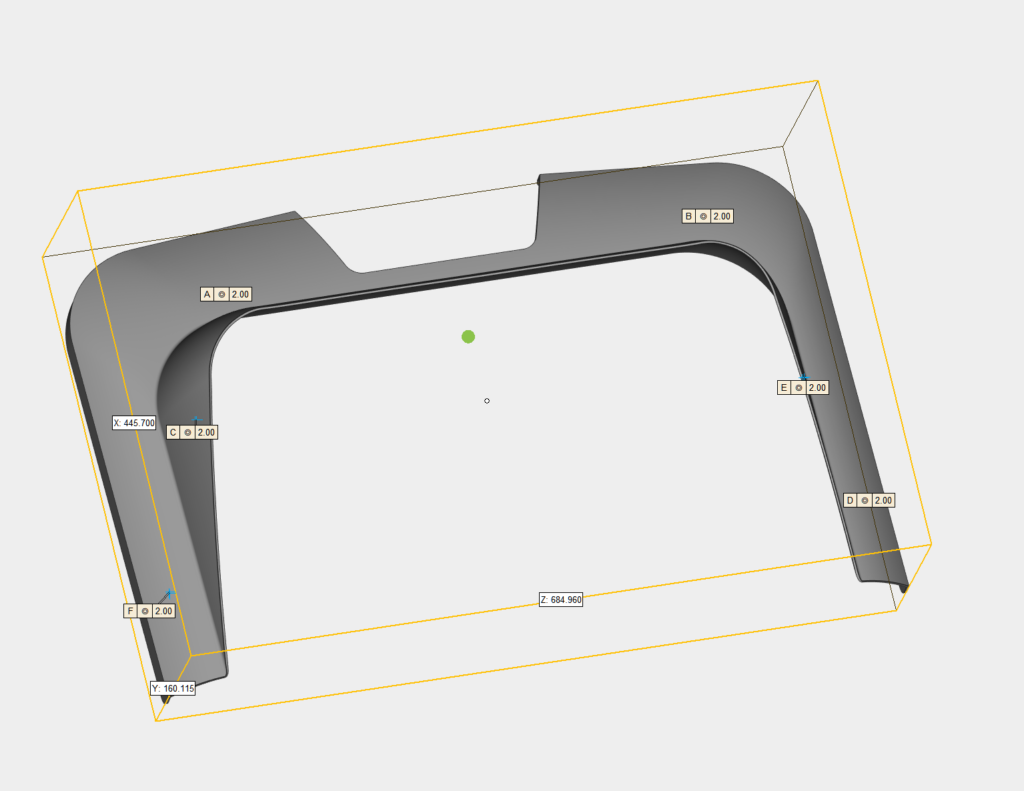
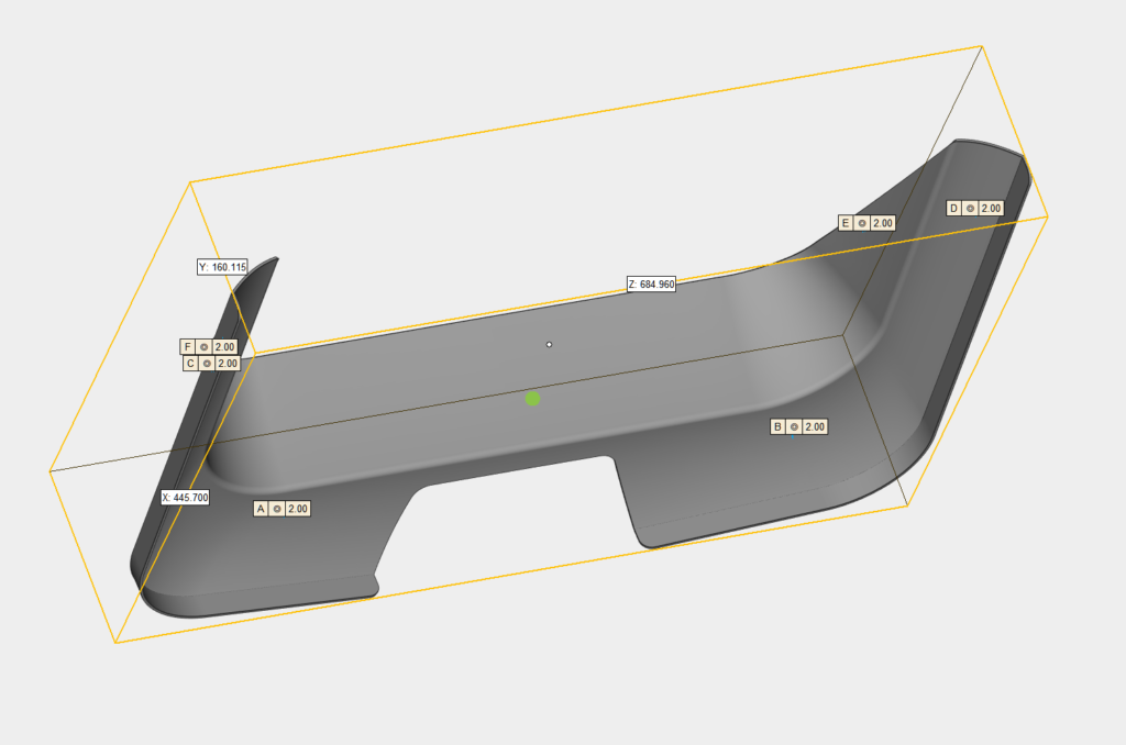
One component. One connected route.
Material
Should the cover use polycarbonate for impact resistance, acrylic for optical appearance, or another transparent material? What thickness will still work after forming and at the mounting points?
Surface
Does the scratch-resistant surface need to survive forming, or should it be applied after the shape is created? Which areas must remain suitable for printing, bonding or handling?
Geometry
What curvature, draw depth, radii, hole positions, trimmed edges and critical dimensions control the tooling and forming method?
Process Sequence
Should forming happen before coating? When are CNC trimming, drilling and printing completed, and how is the finished surface protected between steps?
Assembly
How will the cover meet the frame, gasket, adhesive and hardware? Which interfaces control fit, sealing and mounting accuracy?
Validation
The prototype should confirm geometry, surface condition after processing, assembly fit and the agreed acceptance reference.
These answers create a defined combination of material, surface system, geometry, manufacturing sequence and acceptance reference that can move into prototype work, quotation and repeat production.
Prove the Part Before Production
A prototype is useful when it answers the questions that could become expensive after tooling, coating or production begins. It is more than a sample that looks close to the drawing.
For a formed transparent cover, the prototype can be used to confirm: whether the curvature, trimmed edges and mounting holes fit the assembly; whether the surface remains acceptable after forming, CNC work, printing, bonding and handling; whether the gasket, adhesive and hardware meet the part as intended; and whether the proposed sequence can be repeated without relying on hand correction.
Before the sample is evaluated, the project should identify the part configuration and the reference used for acceptance. Depending on the project, that may be critical dimensions, assembly fit, an approved sample, a surface check or a customer-defined test.
The purpose is to expose what still needs to change while the material, surface system, tooling or process sequence can still be adjusted—before those issues become production rework or a disagreement over what was approved.
Sample · Inspection · Fit Check
Typical Engineering Challenges
Formed part + functional surface
CHALLENGE 01
Curved Part + Functional Surface
Challenge: The part needs a three-dimensional shape and a scratch-resistant, anti-glare, anti-static or other functional surface.
Hidden questions: The surface may change during forming, trimming, printing, bonding or handling.
Variables to define: Substrate and thickness, surface system, coated area, forming sequence, radii, trimming method and the condition that must be checked on the prototype.
Existing part + assembly reference
CHALLENGE 02
Existing Part Replacement
Challenge: A scratched, broken or unavailable acrylic or glass window must be replaced, often without a complete drawing.
Hidden questions: Changing the material can alter thickness, stiffness, hole behavior, gasket compression, adhesive areas and mounting.
Variables to define: Existing part and frame dimensions, hardware, optical area, service environment, required surface function and the reference used to accept the replacement.
Multi-function transparent component
CHALLENGE 03
Transparent Component With Multiple Functions
Challenge: One component must provide visibility while also carrying printing, bonding, sealing, mounting or a functional surface.
Hidden questions: One area or process can interfere with another.
Variables to define: Clear and printed zones, bond and gasket areas, holes and edge geometry, process order, handling protection, assembly fit and acceptance criteria.
These are recurring challenge patterns, not customer case studies or claims of a completed project result.
From Engineering Definition to Repeatable Production
Engineering work should not end with a recommendation or a good-looking sample. Before a transparent component can be quoted, purchased and repeated, the agreed definition needs to be clear enough for the same part to be understood by the customer, production and quality teams.
Material, surface, geometry, sequence, interfaces and acceptance are defined together.
The agreed definition gives purchasing a comparable basis for quotation.
Production and quality teams work from the same sequence and inspection reference.
Future orders and approved changes retain a practical shared reference.
The material and thickness, surface requirement, geometry and critical dimensions; the order of forming, coating, machining, printing and bonding; the approved sample or inspection reference; expected quantity and repeatability needs; and packaging or documentation required for delivery.
This gives purchasing a comparable basis for quotation, gives production a clear sequence to follow and gives both sides a practical reference for future orders or approved changes.
PlsTect’s scope covers transparent materials, functional surfaces, component fabrication and manufacturing, and the related project definition. The customer or OEM retains responsibility for machine-level regulations, system-level risk, final product certification and its own approval requirements.
Frequently Asked Questions
Can PlsTect review a project without a complete drawing?
Yes. An engineering review can start with available information such as an existing part, sample, concept, application requirement, or a preliminary drawing.
The goal is to identify the key material, surface, geometry, manufacturing and assembly considerations before the project is fully defined.
What information should we provide for an engineering review?
Useful information may include the existing drawing, CAD file, sample, material requirement, application environment, expected quantity, surface performance needs, and any current problem with the existing part.
The required level of detail depends on the project stage.
Does PlsTect help select materials and surface functions?
Yes. Material and surface selection are reviewed together with the final component requirements.
Factors such as impact resistance, transparency, surface durability, static control, forming requirements, machining, bonding and assembly conditions may affect the recommended route.
Can PlsTect work from an existing part or sample?
Yes. Existing parts, samples or reference components can be used as a starting point for engineering review.
The review may include dimensional considerations, material alternatives, surface requirements, mounting interfaces, manufacturing feasibility and potential improvement opportunities.
When is prototype validation recommended?
Prototype validation is recommended when geometry, surface performance, assembly fit, forming behavior or final appearance needs to be confirmed before production.
A prototype can help verify the defined manufacturing route and reduce risks before repeat production.
Does PlsTect support production after the engineering review?
Yes. After the component definition is confirmed, PlsTect can support the transition into fabrication and repeat production through appropriate material selection, processing routes, finishing requirements and component specifications.
Start Your Project Review
Share your material, drawing, sample, coating requirement, or use environment. PlsTect can help review the surface function, material route, processing direction, and sample development needs before the project moves further.